Motion sensors are widely used today to activate street or indoor lights, trigger alarms, activate switches, etc. This post presents circuit which turn ON an LED when motion is detected with HC-SR501 PIR sensor. The output of the sensor triggers BC547 transistor which acts as a switch to open the circuit. Then LED will turn on for some time.
Components
| No. | Component | Quantity |
|---|---|---|
| 1. | Power supply (9V) | 1 |
| 2. | HC-SR501 PIR sensor | 1 |
| 3. | 100Ω resistor | 1 |
| 4. | 330Ω resistor | 1 |
| 5. | BC547 transistor | 1 |
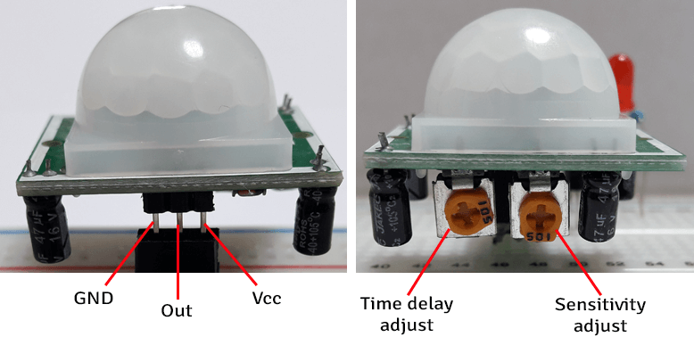
HC-SR501 PIR sensor has three pins: Ground, Output and Vcc as shown in the picture. This sensor also has two potentiometers which can be used to adjust time delay and sensitivity.
Time delay defines how long the voltage of output pin will stay at 3.3V (HIGH) after motion detected. Rotate the potentiometer clockwise to increase time delay (max about 300 seconds) and rotate counterclockwise to decrease time delay (min about 3 seconds). We adjusted time delay to be approximately 3 seconds.
Sensitivity defines the maximum distance for motion detection. Rotate the potentiometer clockwise to increase sensitivity (max about 7 meters) and rotate counterclockwise to decrease sensitivity (min about 3 meters). We adjusted sensitivity to be approximately 5 meters.
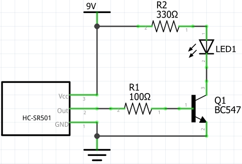
Circuit diagram
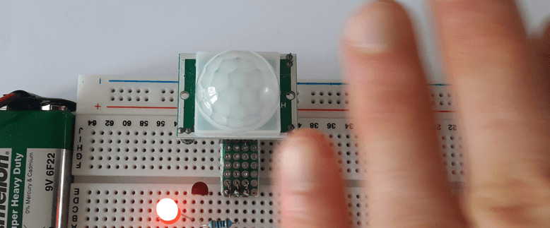
When HC-SR501 PIR sensor detects motion, the voltage of output pin increases to 3.3V and current triggers BC547 transistor. It acts as a switch which opens circuit and turns ON an LED.
The base current of transistor is limited with R1 resistor. The R2 resistor is a current limiting resistor for an LED.
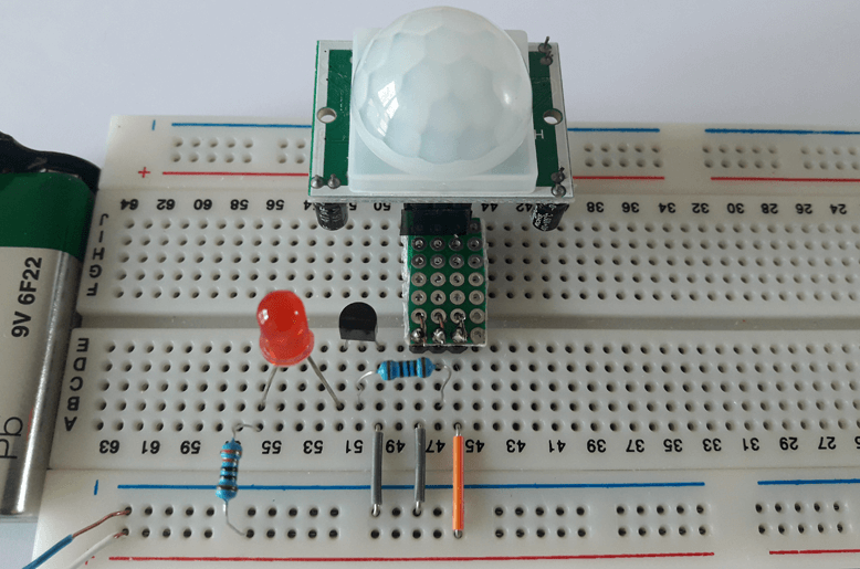
Designed circuit
Circuit is designed on a breadboard. When circuit is power up we need to wait about 30-60 seconds for the HC-SR501 PIR sensor to initialize.
Leave a Comment
Cancel reply