This post presents circuit for blinking two LEDs alternatively. Circuit is based on 555 timer which is used in astable mode. In this mode the output is generated in the form of a square wave. This means that output cycles on and off repeatedly.
Components
| No. | Component | Quantity |
|---|---|---|
| 1. | Power supply (5V - 10V) | 1 |
| 2. | 555 timer | 1 |
| 3. | 1kΩ resistor | 3 |
| 4. | 100kΩ resistor | 1 |
| 5. | 10μF electrolytic capacitor | 1 |
| 6. | 10nF ceramic capacitor | 1 |
| 7. | LED | 2 |
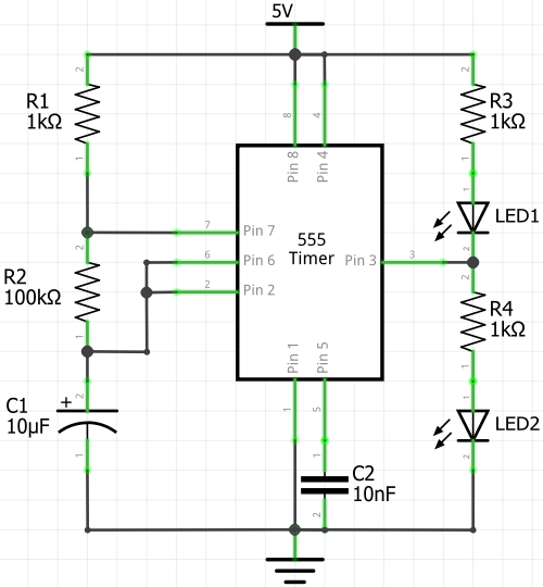
Circuit diagram
The values of R1, R2 resistors, and C1 capacitor affects the blinking rate of the LEDs.
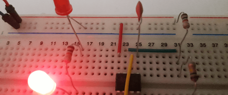
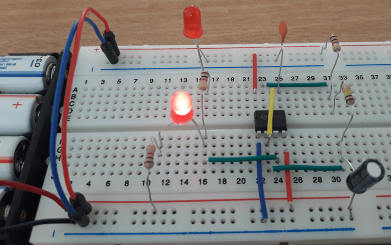
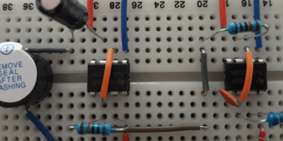
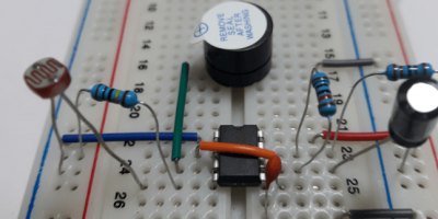
Designed circuit
Circuit is designed on a breadboard.
Leave a Comment
Cancel reply