This post presents circuit of electronic coin toss also known as coin flip circuit or heads or tails circuit. When the push-button is pressed, the LEDs will start blinking fast. One of the LEDs will stay to light up when the push-button is released. Circuit is based on 555 timer that works in astable mode to generate the output in the form of a square wave.
Components
Use two different colored LEDs. For example, the red LED for heads and the green LED for tails.
| No. | Component | Quantity |
|---|---|---|
| 1. | Power supply (9V) | 1 |
| 2. | 555 timer | 1 |
| 3. | 470Ω resistor | 2 |
| 4. | 1kΩ resistor | 1 |
| 5. | 100kΩ resistor | 1 |
| 6. | 1μF electrolytic capacitor | 1 |
| 7. | 10nF ceramic capacitor | 1 |
| 8. | LED | 2 |
| 9. | Momentary push-button switch | 1 |
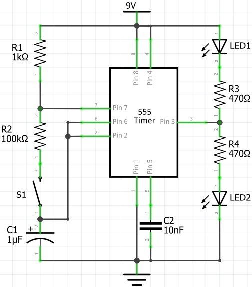
Circuit diagram
The blinking rate of the LEDs depends on the values of R1, R2 resistors, and C1 capacitor.
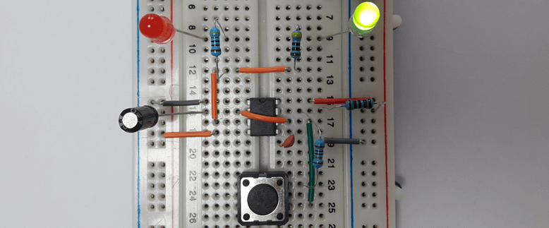
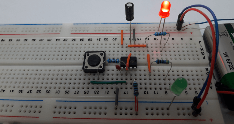
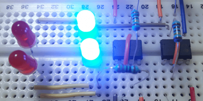
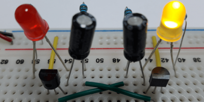
Designed circuit
Circuit is designed on a breadboard.
Leave a Comment
Cancel reply