One of the ways to control an LED is a GUI application which sends commands from PC to microcontroller via serial port to perform required actions.
This tutorial shows how to turn ON/OFF an LED using ESP8266 NodeMCU development board and Qt 5 GUI application.
Components
| No. | Component | Quantity |
|---|---|---|
| 1. | ESP8266 NodeMCU + Micro USB cable | 1 |
| 2. | 330Ω resistor | 1 |
| 3. | LED | 1 |
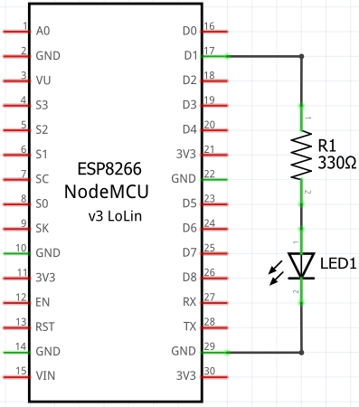
Circuit diagram
A current limiting resistor is connected to the D1 pin on the NodeMCU board. The anode (+) of an LED is connected to the resistor and cathode (-) of an LED to the GND.
ESP8266 NodeMCU code
We will use PlatformIO to build the program for NodeMCU board. Run the following command to initialize new project:
pio project init --board nodemcuv2The command will create project configuration file:
platformio.ini
[env:nodemcuv2]
platform = espressif8266
board = nodemcuv2
framework = arduino
In the setup function, serial communication is initialized and D1 pin is configured as an output.
In the loop function, we checking if the data is available to read from the serial port. If so, we read bytes until a new line character is received and place them into an array. Character array need to be a null-terminated in order to compare it with another character array using strcmp function. So we add a null character ('\0') to indicate the end of the character array. There are two commands on and off which turns ON/OFF an LED.
src/main.cpp
#include <Arduino.h>

const int LED_PIN = D1;
char buffer[10];

bool isEqual(const char* cmd)
{
    return strcmp(buffer, cmd) == 0;
}

void setup()
{
    Serial.begin(9600);
    pinMode(LED_PIN, OUTPUT);
}

void loop()
{
    if (Serial.available() > 0) {
        int length = Serial.readBytesUntil('\n', buffer, sizeof(buffer));
        buffer[length] = '\0';

        if (isEqual("on")) {
            digitalWrite(LED_PIN, HIGH);
        } else if (isEqual("off")) {
            digitalWrite(LED_PIN, LOW);
        }
    }
}
Build project and upload program to the NodeMCU by using this command:
pio run --target uploadQt 5 GUI application
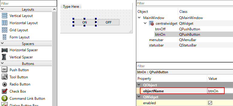
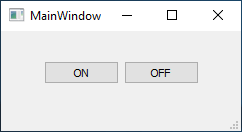
Create a new Qt Widget based application. Using Qt Designer create UI that contains two push buttons. Assign object names btnOn and btnOff to them.
Open project file .pro and add serialport to the QT variable:
QT += serialportIn the header file we added constant which stores the name of the serial port. Also we defined an instance of QSerialPort class.
mainwindow.h
#ifndef MAINWINDOW_H
#define MAINWINDOW_H

#include <QMainWindow>
#include <QSerialPort>

QT_BEGIN_NAMESPACE
namespace Ui { class MainWindow; }
QT_END_NAMESPACE

class MainWindow : public QMainWindow
{
    Q_OBJECT

public:
    MainWindow(QWidget *parent = nullptr);
    ~MainWindow();

private:
    const QString PORT_NAME = "COM8";

    void turnOnLed();
    void turnOffLed();
    void openSerialPort();
    void closeSerialPort();
    void writeToSerialPort(const QByteArray&);

    Ui::MainWindow *ui;
    QSerialPort serialPort;
};
#endif
The openSerialPort member function will be called when application is opened. In this function we set the port name and baud rate. Using open function we try to open the serial port for writing. When application is closing, the closeSerialPort member function is called.
The turnOnLed or turnOffLed member function is called when the corresponding button is pressed. The on or off command with a new line character is written to the serial port to turn ON/OFF an LED.
mainwindow.cpp
#include "mainwindow.h"
#include "ui_mainwindow.h"
#include <QDebug>

MainWindow::MainWindow(QWidget *parent) : QMainWindow(parent), ui(new Ui::MainWindow)
{
    ui->setupUi(this);
    connect(ui->btnOn, &QPushButton::clicked, this, &MainWindow::turnOnLed);
    connect(ui->btnOff, &QPushButton::clicked, this, &MainWindow::turnOffLed);
    openSerialPort();
}

MainWindow::~MainWindow()
{
    closeSerialPort();
    delete ui;
}

void MainWindow::turnOnLed()
{
    writeToSerialPort("on\n");
}

void MainWindow::turnOffLed()
{
    writeToSerialPort("off\n");
}

void MainWindow::openSerialPort()
{
    serialPort.setPortName(PORT_NAME);
    serialPort.setBaudRate(QSerialPort::Baud9600);

    bool success = serialPort.open(QIODevice::WriteOnly);
    if (success) {
        qDebug() << "Serial port is opened";
    }
}

void MainWindow::closeSerialPort()
{
    if (serialPort.isOpen()) {
        serialPort.close();
        qDebug() << "Serial port is closed";
    }
}

void MainWindow::writeToSerialPort(const QByteArray &data)
{
    serialPort.write(data);
}
Testing
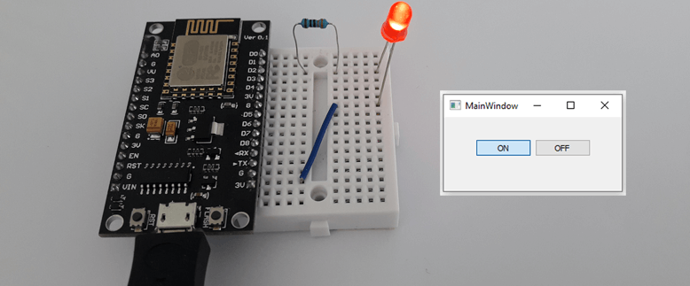
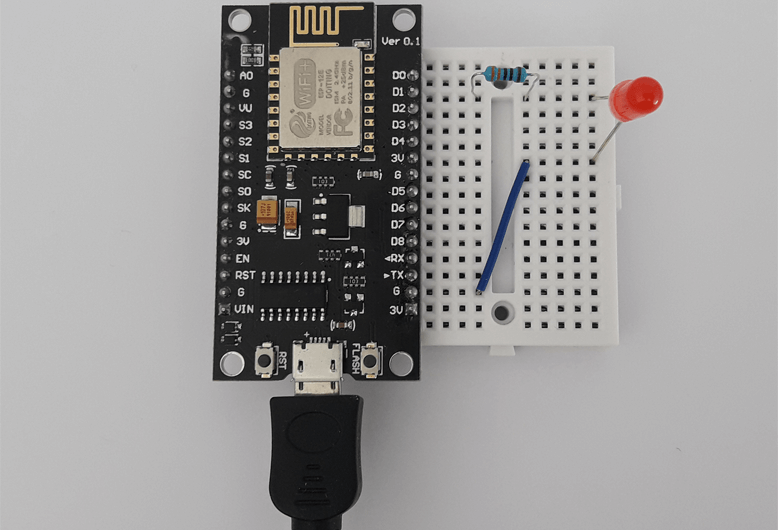
Circuit is designed on a breadboard. NodeMCU is connected via USB to a PC.
Qt 5 application is compiled and executed. An LED turns ON or OFF when corresponding button is pressed.


The 4 Comments Found
Hi i am using linux. but there is i am unable to locate
pio. how to find it ?Hi
Make sure you have installed
pipin your system. Run command to install PlatformIO:sudo pip install -U platformioYou can read more here.
hi i have tried the code the serial port successfully get opened. but is there possible way to blink on board led using same code. because i have not connected external led.
In order to blink onboard LED on ESP8266 NodeMCU, you need to modify the code.
Change line:
const int LED_PIN = D1;toconst int LED_PIN = LED_BUILTIN;.Onboard LED operates in inverted mode. When received the command
on, changeHIGHtoLOW, when received the commandoff, changeLOWtoHIGH.Leave a Comment
Cancel reply